For over 25 years, Omega Optical has been a leading manufacturer of high performance optical interference filters for a wide range of applications in Raman spectroscopy. We have recently developed a series of QuantaMAX laser edge filters to attenuate, or block, scattered energy from reaching your detector, therefore improving the critical signal-to-noise. Combined with advances in laser and detector technology, our Raman filters are part of a revolution in Raman spectroscopy, expanding the use and applications of this analytical method. At the detector, both desired signal and unwanted scatter will be present, with the signal orders of magnitude lower than the scatter.
Scatter is the result of minor irregularities and characteristics of the system optics and application including uncontrolled light from the sample and holder. Longpass QuantaMAX Raman Edge filters are an excellent laser rejection solution when used in a collimated light path on the detector side of the system. These filters attenuate shorter wavelengths to ~0.7 edge wavelength. These filters also transmit 95% of Stokes Raman or fluorescence signal and exhibit very high contrast between the Rayleigh and Raman transmission. Angle tuning is required for optimal performance.
General Overview
Raman spectroscopy provides valuable structural information about materials. When laser light is incident upon a sample, a small percentage of the scattered light may be shifted in frequency. The frequency shift of the Raman scattered light is directly related to the structural properties of the material. A Raman spectrum provides a "fingerprint" that is unique to the material. Raman spectroscopy is employed in many applications including mineralogy, pharmacology, corrosion studies, analysis of semiconductors and catalysts, in situ measurements on biological systems, and even single molecule detection. Applications will continue to increase rapidly along with further improvements in the technology
A Raman signature provides positive material identification of unknown specimens to a degree that is unmatched by other spectroscopy's. Raman spectroscopy presents demanding requirements for the detection and resolution of narrow-bands of light with very low intensity and minimal frequency shift relative to the source. We are committed to supporting this science with optical coatings of the highest phase thickness and resulting superior performance.
About Raman Spectroscopy
The phenomenon of Raman scattering was discovered in 1928 by Indian physicist C.V. Raman, who received the Nobel Prize in physics in 1930 for his work. The first experiments demonstrating Raman scattering were very crude. Sunlight provided the light source, a telescope collected the scatter from the sample, and Raman's eyes served as the detector. Complementary colored glass filters were used to select the color of light striking the sample and to block out the light that was elastically scattered (same wavelength as the incident light) from the sample.
Raman Scattering
When a probe beam of radiation described by an electric field E interacts with a material, it induces a dipole moment, μ, in the molecules that compose the material:
μ = a x E
where a is the polarizability of the molecule. The polarizability is a proportionality constant describing the deformability of the molecule. In order for a molecule to be Raman-active, it must possess a molecular bond with a polarizability that varies as a function of interatomic distance. Light striking a molecule with such a bond can be absorbed and then re-emitted at a different frequency (Raman-shifted), corresponding to the frequency of the vibrational mode of the bond.
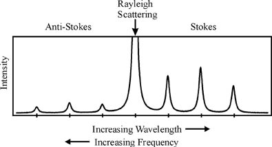
If the molecule is in its ground state upon interaction with the probe beam, the light can be absorbed and then re-emitted at a lower frequency, since energy from the light is channeled into the vibrational mode of the molecule. This is referred to as Stokes-shifted Raman scattering.
If the molecule is in a vibrationally excited state when it interacts with the probe beam, the interaction can cause the molecule to give up its vibrational energy to the probe beam and drop to the ground state. In this case, the scattered light is higher in frequency (shorter wavelength than the probe beam). This is referred to as anti-Stokes Raman scattering, which under normal conditions is much less common than Stokes scattering. The most common occurrence is that light is absorbed and re-emitted at the same frequency. This is known as Rayleigh, or elastic scattering.
Both Rayleigh and Raman scattering are inefficient processes. Typically only one part in a thousand of the total intensity of incident light is Rayleigh scattered, while for Raman scattering this value drops to one part in a million. Thus, a major challenge in Raman spectroscopy is to attenuate the light that is elastically scattered in order to detect the inelastically scattered Raman light.

Probe Laser
The frequency of a Raman shift is independent of the laser wavelength used for excitation. For example, diamond gives a Raman peak that is 1331 cm-1 from the laser line whether excited by an argon ion laser in the visible or by a Nd:YAG laser operating in the near infrared. The intensity of the Raman signal, however, is inversely proportional to the 4th power of the laser wavelength. For example, the Raman signals produced with the 457nm line of an Ar+ laser are nearly 30 times larger than those produced with a 1064nm Nd:YAG laser.
There are often other good reasons to choose one laser excitation wavelength or wavelength range over another. One important consideration is fluorescence interference from the sample. Since fluorescence is a much more efficient process than Raman, it is difficult if not impossible to obtain Raman spectra at laser wavelengths where the sample fluoresces. Interfering fluorescence can often be avoided by exciting at near-infrared wavelengths that are not energetic enough to cause the electronic excitation of the molecule that leads to fluorescence.
As a result, Raman measurements in the near-infrared, most commonly at 1064nm, have become popular in the past few years. Due to the inverse fourth-power relationship between Raman intensity and laser excitation wavelength, signals obtained at near infrared wavelengths are much weaker and the technique suffers in sensitivity. The interferometric Fourier Transform (FT) method is generally employed at near infrared wavelengths to improve signal-to-noise ratios.
Another way to avoid fluorescence, first demonstrated by Sandy Asher in 1984, is to use a UV laser probe beam. At wavelengths < 260nm, there is effectively no fluorescence interference. An added benefit is the inherently strong signal in the UV due to the wavelength dependence of Raman intensity. For these reasons, UV Raman is a very powerful technique that is gaining in popularity.
When the probe laser beam frequency is close to or in resonance with an allowed electronic transition in the molecule, there is a pronounced enhancement of the Raman signal. This is known as resonance Raman scattering. By choosing a probe laser wavelength that overlaps an absorption band of the molecule, one can obtain a Raman signal that is enhanced by as much as a factor of 108.
Wavenumber Shift
Raman spectra are most often presented in units of wavenumber shift. This is defined as the difference in wavenumbers between the Raman scatter and the probe laser. Stokes shifts are defined as positive wavenumber shifts (red of the laser line), and anti-Stokes shifts are defined as negative wavenumber shifts (blue of the laser line). Units of wavenumbers are inverse cm (cm-1). Since Raman scatter can be very close in wavelength to the probe laser (for example, monitoring scatter at 519nm while illuminating with a 514.5nm laser), wavenumber shifts provide a convenient scale for Raman spectroscopy.
In absolute terms, the 514.5nm laser line corresponds to 19,436 cm-1. Stokes Raman scatter 200 cm-1 from the 514.5nm laser line corresponds in absolute terms to 19236 cm-1 or 520nm. Anti-Stokes scatter 200 cm-1 from the 514.5nm laser line likewise corresponds to an absolute value of 19,636 cm-1 wavenumbers, or 509nm.
The frequency of the Raman shift for a particular vibrational mode is determined by the force constant of the bond and the reduced mass of the molecule. Some generalizations can be made about the expected frequency of a Raman band based on the functional group of the molecule. The 1500 cm-1 to 400 cm-1 frequency range is known as the fingerprint region. Correlation charts and collections of known Raman spectra are available in order to identify unknown compounds. Low frequency Raman modes (below about 400 cm-1) are generally associated with metal-ligand bonds. If one is interested in studying very low-frequency Raman modes which lie close to the laser line, it is important to choose a filter or filtering technique that provides a sharp transition between deep blocking of the Rayleigh scatter and transmission of the Raman signal.
Raman Filter Needs
Laser Line “Clean Up”
It is usually necessary to "clean up" the laser output, which may consist of discrete plasma lines or broadband fluorescence background in addition to the principal laser line. If the laser is delivered to the sample with an optical fiber, it is especially critical to remove the Raman modes and fluorescence that are excited in the silica fiber by the laser.
Background removal can be accomplished in several ways. If there is sufficient space between the laser output and sample, spatial filtering may be used. In this method, an optical element (Pellin-Broca prism, for example) is used to disperse the laser output, which then travels some distance and passes through an aperture. Ideally, this physically blocks all but the laser line of interest. Another option for cleaning up the laser beam is to send it through a monochromator set to pass only the line of interest. This has the disadvantage of low throughput of the laser line. Perhaps the simplest and most cost-effective method is the use of an interference filter which passes only the laser line with transmission usually > 80%. Interference filters are also known as laser line filters or bandpass filters.
Blocking Rayleigh Scattering
In order to obtain high signal-to-noise in Raman measurements, it is necessary to block Rayleigh scattering from reaching the detector while transmitting the Raman signal. It's possible to use a double or triple grating spectrometer to accomplish rejection of the background signal. However, this results in low (~10%) throughput of the desired Raman signal. In many cases a better alternative is to use a Raman notch or Raman edge filter. Notch filters transmit both Stokes and anti-Stokes Raman signals while blocking the laser line. Edge filters (also known as barrier filters) transmit either Stokes (longpass) or anti-Stokes (shortpass).

Important considerations in the choice of a notch or edge filter:
1. How well does the filter block out the Rayleigh scattering? Depending on the geometry of the experiment and the sample, a blocking of > OD4 at the laser line is usually sufficient.
2. How steep is the edge, or transition from blocking to transmitting? The steepness of the edge required depends on the laser wavelength and the proximity of the Raman shifted signal of interest to the laser line. If the laser wavelength is 458nm, one would require > OD4 blocking at 458nm, and as high as possible transmission only 4nm away (at 462nm) in order to see a Stokes mode 200 cm-1 from the laser line. If the laser wavelength is 850nm, one would require blocking at 850nm and transmission at 865nm (15nm away from the laser line) in order to detect a signal at 200cm-1. Therefore, the slope of a filter that is required to look at a low frequency mode is steeper at bluer laser wavelengths.
Angle Tuning Narrow-Band Filters
Narrow bandpass filters can be used for Raman imaging applications in which a high signal throughput is required for a specific Raman mode. The concept is based on the fact that the central wavelength of a narrow bandpass filter blue-shifts with increasing angle of incidence. A single bandpass filter can cover a wavelength range in excess of 10% of the central wavelength at normal incidence. Therefore, an entire Raman spectral region can be scanned by selecting a few tunable narrow-band filters with different bandpass wavelengths and continuously tuning their angle of incidence. Bandpass filters can be used in this way for the precise scanning of Raman spectra and will provide high throughput, high resolution, and low image distortion, superior to the dispersive or diffractive filtering of images.
UV Raman Edge Filter Capabilities
These filters, produced using Omega Optical's proprietary ALPHA™ technology, exhibit steep slopes, deep blocking of the laser line, and high throughput of the Raman signal. They are compact and exhibit very high contrast between the Rayleigh and Raman transmission. Constructed of an exposed, hard oxide coating on an optical quality substrate and manufactured using Ion Assist Deposition (IAD), these filters are extremely durable and exhibit no detectable wavelength shifting under variable moisture conditions. UV Edge filters have slopes as steep as 5-Decade slope factors at 3%.
The 5-decade slope factor (5) is defined by:

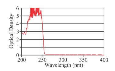
where λ OD5 is the wavelength at which optical density 5 is achieved, and λ OD0.3 is the wavelength at which the optical density is 0.3, or equivalently, the transmission is 50%. Example: a filter designed to block the 248nm laser line at OD 5 will transmit 50% at 256nm. Currently we produce filters for laser wavelengths as low as 229nm and are continuously pushing this limit to shorter wavelengths.
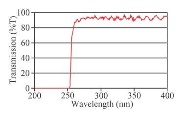
UV Edge Filter Transmission Curve

This is an example of a UV longpass edge filter designed to block 248nm.
UV Edge Filter Blocking Curve

This is an example of a UV longpass edge filter designed to block 248nm.
Raman Microscope Laser Reflector
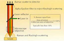
Designed for use in an epi-illumination geometry Raman microscope, the laser reflector is an image quality AR-coated glass element with a centered 2mm diameter aluminum mirror. Mounted at 45°, it reflects the laser into the objective, and then transmits all but a small fraction of the Rayleigh and Raman scattered light collected with the objective. For example, using a 40X objective having a numerical aperture of 0.8 and a focal length of 4mm, only 3% of the Raman signal is lost upon transmission through the laser reflector. This loss is related only to the size of the mirror and the collection properties of the microscope objective. Used with an ALPHA-Epsilon edge filter for Rayleigh rejection, this allows the measurement of Raman lines very close to the laser wavelength with little loss in signal throughput.

