Omega has been manufacturing UV filters for over 50 years. UV light (in the 200 nm - 400 nm range) has many commercial and consumer-level applications. UV light can be used in photolithography or dentistry to photoset polymers, and in biomedical applications to excite molecules during surgery. It can be used to measure DNA and to sterilize our water and the air we breathe. While useful for many things, it can also be harmful. UVA and UVB can cause sunburns and skin cancer, while the shorter wavelength UVC light can cause corneal damage in the eye. Because UV light is invisible to our eyes, the natural aversion response (looking away when something is too bright) does not work to protect us. Make sure you follow eye-safety guidelines when working with UV light sources.
Jump to:
Challenges for UV optical filter manufacturers
Working in the UV (less than about 400 nm) is a challenge for filter manufacturers, because many of the commonly used materials begin to absorb light at these wavelengths. Most interference filters are designed with the assumption that light is only transmitted or reflected and not absorbed. Another challenge for the short pass and bandpass filters is wide-wavelength blocking. Simple filter designs only have blocking up to ~20% of the center wavelength - more extensive blocking can be accomplished by adding a metal layer which significantly reduces the %T in the transmitting region, adding a colored glass absorbing filter, or by adding dielectric layers (for instance, adding a short-pass filter design to the other side of the substrate).
| Common Name | Chemical Formula | Wavelength cutoff (nm) |
|---|---|---|
| Silica | SiO2 | 180 |
| Alumina/ sapphire | Al2O3 | 200 |
| Hafnia | HfO2 | 240 |
| Zirconia | ZrO2 | 270 |
| Magnesium Fluoride | MgF2 | 140 |
| Aluminum Fluoride | AlF3 | 150 |
| Lanthanum Fluoride | LaF3 | 170 |
| Yttrium Fluoride | YF3 | 200 |
UV Filter Subtypes
UV Rejection Band (RB) or Notch Filters
Shop UV Rejection Band Filters
Notch filters are designed to reject specific wavelengths so the absorption properties of the materials are less important for these designs and can be useful in some respects. These can be designed to work at angle (below is an example designed to work at 45 deg) for combined steering and wavelength management or at normal incidence.
Applications of UV Notch Filters
- laser rejection
- Mercury lamp line rejection
UV Bandpass (BP) Filters
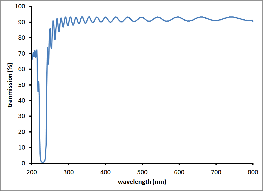
The traditional design of bandpass filters in the UV involves induced transparency in a metal (usually Al or Ag). These filters are very inexpensive to produce, comprising only a handful of layers and providing high blocking over the entire visible wavelength range. The disadvantages include low transmission (often under 20%) and spectral edges that are not very steep.
Sputtered or ion-assisted PVD oxide-based designs can transmit over 80% down to about 250 nm and fluoride-based designs can transmit even lower. Below about 200 nm, measurements become difficult as atmospheric molecules begin to absorb. Special equipment is required to make measurements at very low wavelengths. The difficulty in producing high-quality UV bandpass filters is typically in trying to block the full visible range. The wider the blocking range, the thicker the thin-film stack and the more expensive the filter will be. Sometimes, absorption glass can be used for visible light blocking for bandpasses above about 250 nm without substantially influencing the transmission performance.
Applications of UV Bandpass Filters
- Astronomy
- Calcium II K-line (393.4nm) narrow band
- other
- Biomedical applications
- 260/ 280 DNA ratio
- Flow cytometry (375, 355, 320 nm lasers- scatter channels or laser cleanup)
- Fluorescence imaging
- Intrinsic chromophores (tryptophan, etc)
- Calcium imaging (indo)
- other
- Photolithography
- I-line filters (365 nm)
UV Longpass (LP) Filters
UV absorption can be an advantage in designing UV Long Pass filters because some of the OD blocking can be provided by absorption rather than reflection. Sharp cut-on edges can be optimized using traditional interference design techniques.
Applications for UV Longpass Filters
- Minimize UV damage
- Plastics become yellow and brittle over time if not protected
- DNA – maximum damage occurs at 265 nm
- Fluorescence – emission filters and dichroic filters
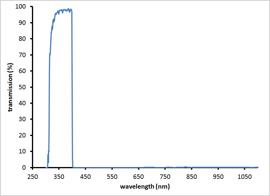
UV Shortpass (SP) Filters
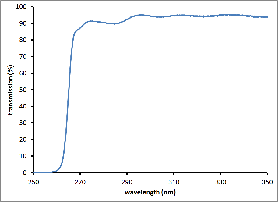
The minimum specified wavelength dictates whether oxide or fluoride materials are used for these filters. As in the UV band pass filters, blocking of all visible wavelengths increases the complexity and cost of the filters. In the sputtered oxide filter below, the short wavelength edge (at about 280 nm is due to absorption of the coating materials).
Specialty UV Filters
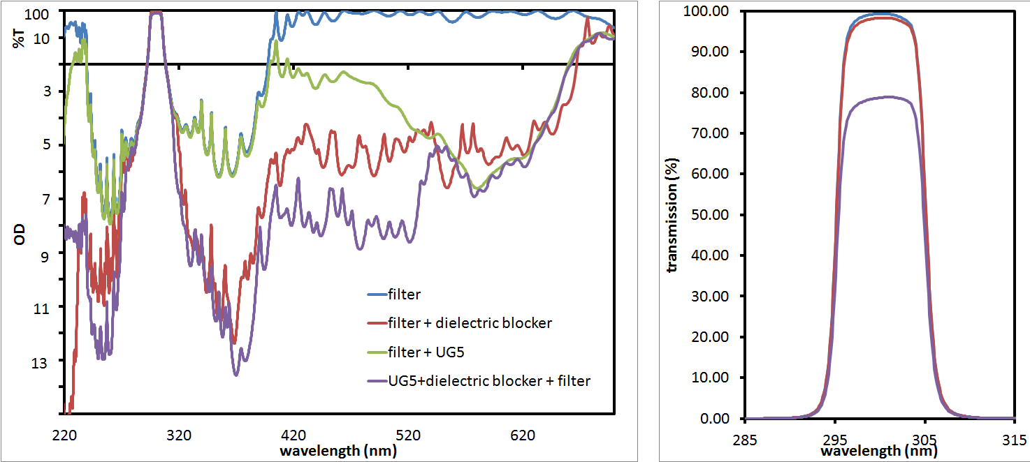
UV filters with Limited Blocking
Many common UV light sources are comprised of a number of bright "lines" or wavelengths, with relatively low emission levels between them. Common UV lamps include gas discharge lamps (like low- and medium-pressure Mercury lamps) and excilamps which emit light due to excimer or exciplex formation in the excited state of the gases within the lamp housing (Xenon, Krypton Chloride, etc). Blocking in these lamps can be tailored to provide deep blocking at only the wavelengths of interest, while providing high throughput at the desired wavelength. Unlike wide-band blocking, achieved with the metal coatings, absorption glass, or very thick interference stacks described above, our engineers can optimize the design for your desired wavelength, minimizing cost and maximizing performance.
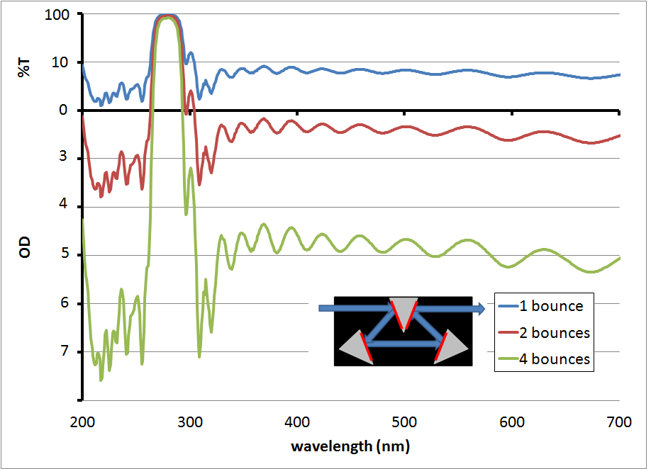
Reflective Filter Assemblies
In some cases, it is easier to design a reflective filter in the UV, which in transmission looks like a notch (or rejection band) filter, but when used in a reflective assembly as shown below, can attain high effective transmission over a narrow wavelength range. In these designs, the blocking OD is additive as the number of bounces increases, while the effect on %T is small.